SPICA TA
REPAIR DO IT YOURSELF
This is a
description for repairing the Spica TA with special thanks to Wim Neijenhuis,
who did most of the technical thinking and practice.
The
advantage of the adjusting screw is:
1) Easy to
adjust after repairing the TA
2) The
possibility of re-adjusting in case of a minor leak in the system.
 Materials used:
1) Copper
tube (for sleeves) Ø 4x1mm price: ¤ 0.60
2) 3-way
T-coupling 4mm with compression fitting
price: ¤ 3.90
3)
Compression chamber with adjusting screw
price: ? It was home
made by a friend as a
favour.
4) Brake
fluid
5) Syringe
with needle
6) Metal
saw
7) Small
gas-burner/torch
Repairing the TA:
Cut the
capillary tube of the TA about 50mm from the beginning (from the plunger end).
Clean the
tube ends using fine sandpaper so that you can make a good solder joint.
Cut two
23mm copper tubes which you will use as sleeves. The diameter of the sleeves
has to be enlarged using a 2mm bore.
Slide the
sleeves over the capillary ends, letting 7mm of the capillary stick out (this
is to prevent the solder flowing in and obstructing the capillary).
Solder the
sleeves to the capillary and cut off the 7mm of the capillary that sticks out.
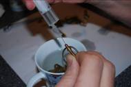 Put the expansion bulb in warm water
till fluid comes out of the capillary (to make sure there is no air left in the
tube) Then put the bulb in cold water while constantly filling it with a
syringe filled with brake fluid.
Put the expansion bulb in warm water
till fluid comes out of the capillary (to make sure there is no air left in the
tube) Then put the bulb in cold water while constantly filling it with a
syringe filled with brake fluid.
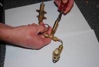
Connect the
end of the capillary from the expansion bulb to the 3-way T-coupling.
Fill the
T-coupling with brake fluid using the syringe.
Connect the
compression chamber to the T-coupling and fill with brake fluid.
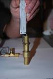
Turn in the
adjusting screw in the compression-chamber, holding the open end of the
T-coupling upwards till fluid comes out..
 Fill the capillary connected to the
piston housing using the syringe and connect to the T-coupling.
Fill the capillary connected to the
piston housing using the syringe and connect to the T-coupling.
Now all
components are filled with brake fluid and connected.
Adjusting
the TA:

For the
adjustment of the TA we used the diagram on Bruce's website.
We worked
in a room at 19.9º C, so according to the diagram the extension of the piston
has to be 23mm.
 The only thing to do now is to turn
in the adjusting screw until the extension of the plunger is 23mm.
The only thing to do now is to turn
in the adjusting screw until the extension of the plunger is 23mm.
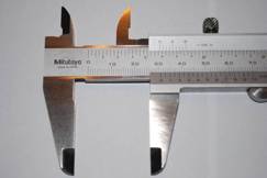
 Finally we checked the max.
extension of the plunger in boiling water. It was 31mm.
Finally we checked the max.
extension of the plunger in boiling water. It was 31mm.
And also
the extensions at intermediate temperatures were exactly according to the
diagram.